Forze Hydrogen Racing is a student team whose mission is to show the potential of green energy — specifically hydrogen energy — through the design, production and racing of fuel cell powered vehicles. In less than 13 years, the team has evolved from building hydrogen go-karts to full-size LMP3-based hydrogen electric racing cars — supported by hard- and software from SEGGER.
You can find more about the team and the car itself at the end of the article.
Forze’s software department has two main projects: Programming the car’s embedded systems and the telemetry of all data generated by the car.
The embedded system’s job is to collect and transport all data produced by various sensors for processing and to control the actuators — effectively making the car drive.
SEGGER, with its vast industry expertise, is an integral partner in the embedded systems project and provides tools to design and build the system.
The development team uses J-Link debug probes provided by SEGGER to flash and debug nodes. The architecture of the car and the individual nodes and their function will be described in detail later.
J-Links are first used in the development phase to flash development kits. In the production phase, they are used to flash the prototypes of the in-house developed nodes, where they are utilized to find any faults in the PCBs. Finally once the car is completed, J-Links are then used at track tests and for general car software updates.
SEGGER’s embOS library — part of emPower OS — runs on every node in the car. The RTOS is probably one of the most critical pieces of software running on the car, essentially controlling all the tasks being performed on various nodes. In a racing car, reliability and performance are the most important factors, among many other requirements: Certified by TÜV SÜD, embOS-Safe complies with the functional safety standards IEC 61508 SIL 3 and IEC 62304 Class C. This certification highlights the high quality standards of embOS development processes. Ultimately, this makes embOS even easier to use in safety-critical key market segments. It guarantees 100 % deterministic real-time operation for any embedded device with zero interrupt latency. Tasks can easily be created and safely communicate with each other, using communication mechanisms such as semaphores, mailboxes, and events.
Depending on the requirements, the architecture in a race car is based on different hardware platforms. This is where the flexibility of embOS comes into play: All popular cores and compilers are already supported, including over 500 board support packages for the embedded market. The kernel is completely written in C and can be ported to any processor for which an ANSI compliant C-compiler exists.
The success of the development team that uses SEGGER’s J-Link and embOS is seen in the racing results: Their latest car, the Forze 8, beat 42 petrol powered cars and came in second place in the 2019 Dutch Supercar Challenge. This makes it the fastest hydrogen electric racing car that has competed in an official race. Currently the team is in the development process of the next car, the Forze 9. With this car, Forze aims to redefine almost all systems from the ground up, using knowledge accumulated throughout the years to build the most powerful hydrogen racing car ever built, and to race in the GT class — while of course still using critical components from SEGGER to achieve success.
Architecture of the latest Forze 8 racing car
Forze 8’s embedded systems consist of a modular, distributed network of nodes with different functions. These nodes contain an Arm Cortex-M4 microprocessor, specifically a LPC4357 OEM board manufactured by Embedded Artists. This processor contains a floating point unit and runs at 204 MHz, making it a suitable platform for the control systems. The control node also contains some power supply circuitry and a CAN bus interface.
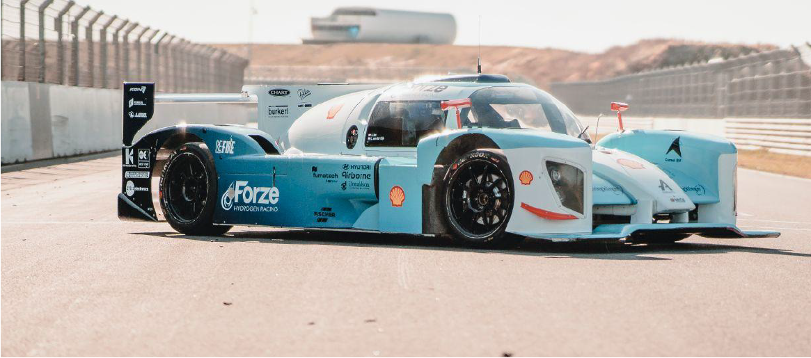
The Forze 8 uses a decentralized system. Every node has its own function. Some are responsible for a whole subsystem, such as the traction system or fuel cell system, others simply provide an interface to nearby sensors and actuators. The picture below shows a typical node inside the car. For readers interested in more details, Appendix A provides a listing of all nodes with their specific function.
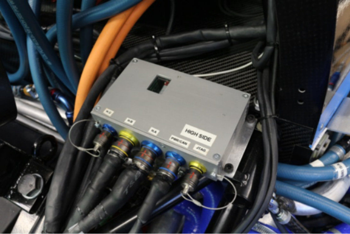
The Power Distribution Unit distributes low voltage power and monitors safety critical systems.
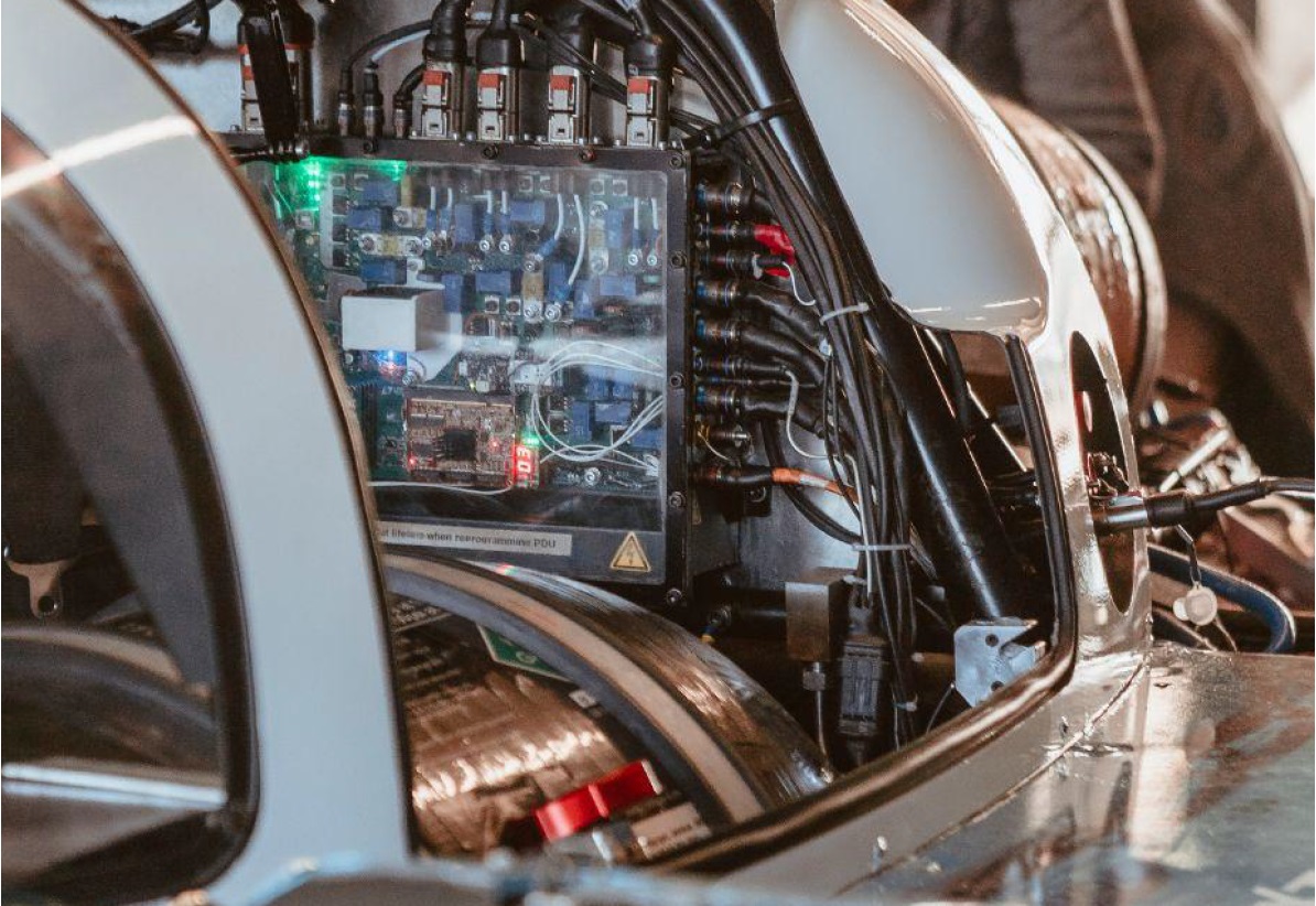
One further point of notice is the human-device interface (also known as the steering wheel). The logic of the steering wheel is handled by the dashboard node, while the wheel itself has its own processor to focus on the screen.
The nodes form a network of small computers and combined they control over 300 sensors, and actuators in more than 200 devices. All these nodes, sensors and actuators are connected by a wiring harness with a total cable length of over 1.5 km. It’s obvious that a trouble-free interaction of all these components is essential for the smooth operation of the race car. SEGGER’s embOS RTOS running on all described nodes guarantees 100 % deterministic real-time operation and due to its reliability and safe communication mechanisms that at the end not just the RTOS, but the whole Forze 8 simply works!
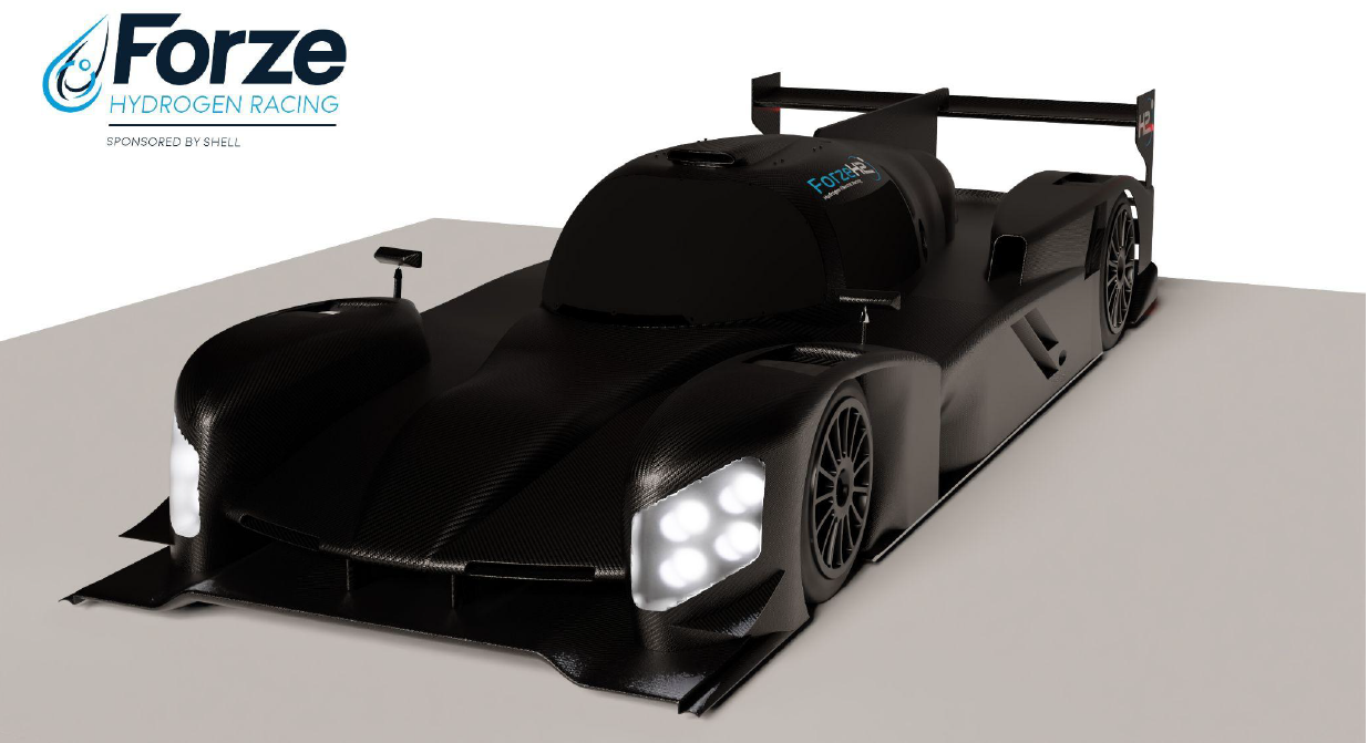
Forze 9 — Innovations push speed limit to 300 km/h
The embedded system of the Forze 9 is currently in the development stage, and slowly transitioning to the production phase. The first nodes have been produced and debugged, but there still remain a lot of nodes to test and produce. The following picture shows a render of the future car.
While the embedded systems of the Forze 8 had a decentralized design, the decision was made to switch to a centralized design in the Forze 9. This means that instead of 10 specific nodes there are 4 types of nodes. Also, there will be 4 CAN busses instead of 2. The different components of the Forze 9 embedded system, whose software also runs on SEGGER’s embOS RTOS, are as follows:
Central Processing Stack (CPS)
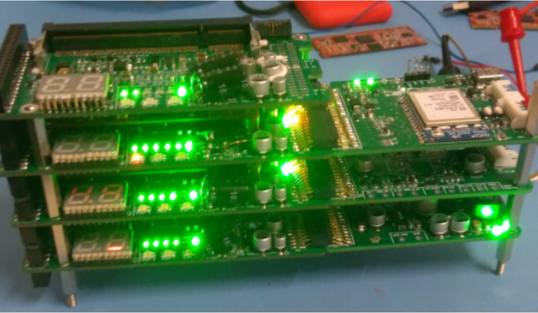
The CPS is the brain of the Forze 9. Here all data collected throughout the car, is gathered and processed appropriately. The CPS consists of 8 PCBs all stacked upon each other. Each PCB carries an Arm Cortex-M7 microprocessor, specifically an i.MX RT1062 OEM board once again manufactured by Embedded Artists. Furthermore, each carrier PCB has access to a module PCB that has task-specific circuitry. These modules are slid from the side into the connector on the carrier PCB. Internally the CPS cores use a CAN-FD bus for communication.
Every node in the CPS has its own tasks and different code is run on every core. Again, for readers interested in more details, Appendix B provides a list that briefly describes each node and its responsibilities. The following picture shows a prototype of the CPS.
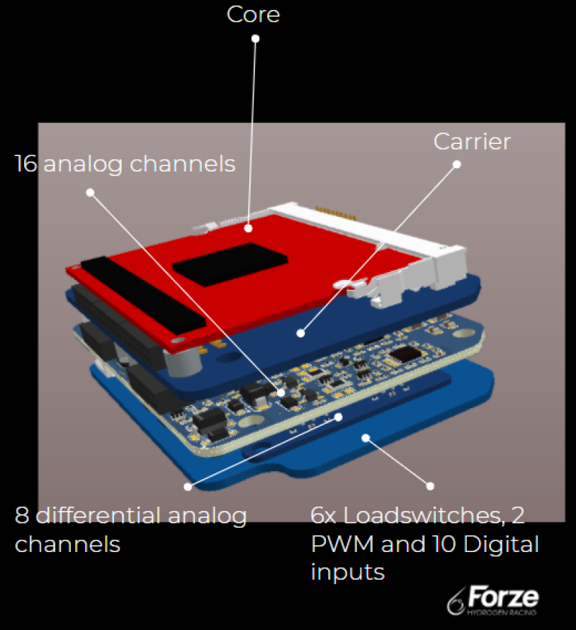
Distributed Interfacing Node (DIN)
The DINs (see picture below) are essentially the nervous system of the car. The DINs are generic nodes scattered throughout the car connected to one of the 4 CAN busses, the various sensors and the actuators. Essentially the CPS sends a configuration to the DINs on startup meaning that every DIN runs the same code. The DINs have 4 PCBs stacked on top of each other. They also have a Cortex-M4 core as used in the Forze 8. Currently the first DIN prototypes are being assembled and prepared for testing.
Nibble nodes
During the design phase it was discovered that there are some technologies that only a few components use (e.g. LIN, isoSPI). As the DINs are generic nodes, omitting these technologies would save a lot of overall space. For this purpose, the nibbles were designed (Pic 7).
The nibbles are essentially very small single-PCB nodes sporting a simple Arm Cortex-M0 core acting as “translator”. The nibbles are connected to a CAN bus, and for example, if a specific component interacts with LIN it will map this message to a CAN message.
Innovations implemented in Forze 9
Besides the improvements to the embedded system, the team has developed some interesting innovations at car level. As a result the expectation is that the Forze 9 will achieve a maximum speed of 300 km per hour.
The team found a clever way to recover kinetic energy on the straights. That energy is stored in a buffer, when the car steers into a corner the energy is converted back into speed when the car drives out of the corner. That is a huge advantage compared to regular combustion cars.
Also new to the Forze 9 is the four-wheel drive and the technology that ensures that all four wheels can be driven independently of each other. So, in a corner the outer wheels turn just a little faster than the inner ones and as a result, the forces that the wheels exert on the road are distributed much better.
Furthermore, the Forze 9 gets two so-called balance of plants, and therefore two fuel cells, instead of one. These are the power units of the car, the systems that convert the hydrogen into electricity that drives the car. And this car is getting two because it offers engineering benefits. The team puts all its knowledge into developing the first balance of plant which is extensively tested and developed. This optimized power source will then “only” be duplicated.
Once completed, it is expected to be the world’s fastest fuel cell electric racing car and a profound breakthrough in sustainable racing. The Forze 9 will have an acceleration from 0-100 km/h in less than three seconds. Weighing 1,500 kg, the Forze 9 will carry two fuel cell systems with a total combined output of 240 kW, and an accumulator with a maximum boost power of 600 kW.
Conclusion
Forze is an exciting team made up of some of the brightest young minds, and with a proven pedigree of bringing fuel cell mobility to the race track. Using SEGGER’s development tools and software, the team will push the boundaries of what’s possible in the development of zero-emissions racing.
Learn how to setup SEGGER embOS RTOS.
About Forze
Forze is a racing team that consists of 25 full-time and 35 part-time students affiliated with the TU Delft and together, they design and develop a racing car that runs on hydrogen. They do not compete in student races, they join official GT-races on world-renowned tracks like Zandvoort and Assen.
The team wants to compete in the GT class, and to beat Ferrari and Lamborghini race cars with internal combustion engines.
Appendix A: List that briefly describes each embOS-powered node and its responsibilities in Forze 8
Dashboard node (Master): Runs the Master-FSM, determines the state of the car. Also runs the driver interfacing (dashboard, steering wheel and pedal box).
High Side node: Controls all the high voltage systems on the high side of the HV DC/DC Converter. The Accumulator side monitors voltages, currents, temperature and insulation resistance in the HV system, including in the accumulator and switches contactors in the HSJB and RESS extension.
Low Side node: Controls all the high voltage systems on the low side of the HV DC/DC Converter (the Fuel Cell side).
Anode node: Controls all systems on the anode side of the fuel cell stack (the side where hydrogen goes in).
Cathode node: Controls all systems on the cathode side of the fuel cell stack (the side where oxygen goes in).
Front node: Interfaces with vehicle dynamics sensors (suspension members, brake temperature, etc) and driver support systems (GPS, ABS, power steer, etc.).
Rear node: Interfaces with vehicle dynamics sensors (suspension members, brake temperature, etc.) and motor controllers.
Data acquisition node: Provides telemetry and logging to an SD card that can be read out via USB.
Telemetry node: Contains a modem operating at radio frequencies wirelessly sending the data the car generates at real time.
Appendix B: List that briefly describes each embOS-powered node and its responsibilities in Forze 9
Init A&B: provides the initialisation of the A and B CAN buses, filters out the messages meant for the other cores and provides the driving of the larger devices on these buses.
Init C&D: same as the previous but for the C and D CAN buses.
FSM: runs the Finite State Machine that controls the car.
Control FC: runs the control of the Fuel Cell.
Control TC: runs the Traction control.
UHF telemetry: provides control for the medium-range UHF telemetry.
4G: provides control for the 4G telemetry.
Wifi: provides control for the Wifi communication.
The different modules used are as follows:
Diagnostics: contains seven segment displays to show the status of the CPS (sits on top and is not connected to any carrier board).
CAN A/B: provides communication and isolation for the A and B CAN buses.
CAN C/D: same for the C and D buses.
Battery Management System: contains the batteries for backup power and manages the recharging.
Power: provides power for the CPS from either the USBC connection or the rails.
Fan: cools the CPS.
UHF telemetry: provides the radio for UHF communication.
4G Raspberry Pi: provides a raspberry pi 4 CM and 4G modem for 4G communication.
Wifi Raspberry Pi: provides a raspberry pi 4 CM for Wifi communication.
Appreciating the time and effort you put into your website and in depth information you provide. It’s awesome to come across a blog every once in a while that isn’t the same unwanted rehashed information. Great read! I’ve bookmarked your site and I’m adding your RSS feeds to my Google account.
Thank you Byron, it’s a pleasure to serve our customers and business partners as much as possible !
I like reading an article that will make people think. Also, thank you for allowing for me to comment!
It’s always a pleasure to receive feedback from customers and business partners, therefore thank you for your positive feedback!